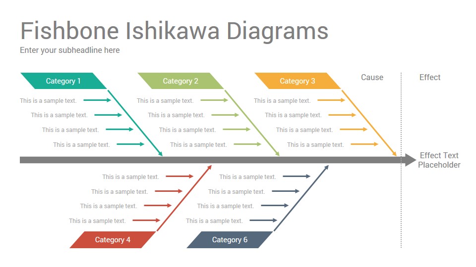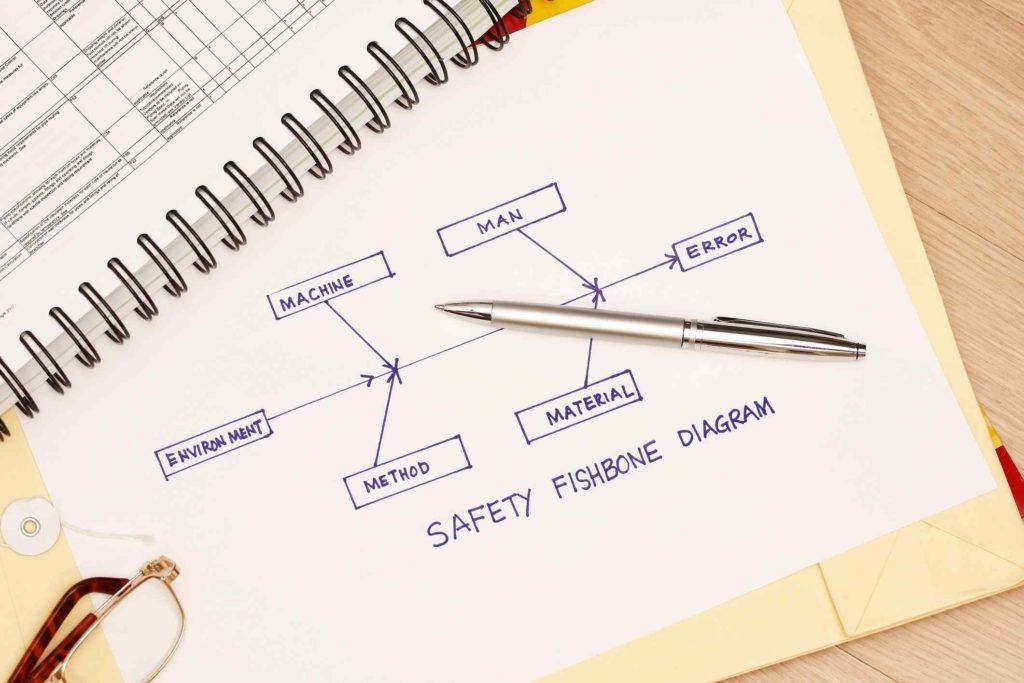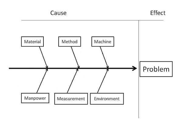

Here we change modes and needs a little time for our brains to shift gears. When you are out of ideas, take a break to clear everyone’s head. If you find there are branches of the diagram that are missing, delve into that area further, asking questions “Is it possible that the environment has affected our problem” too hot, too cold, too wet? Continue until the team runs out of ideas. Also add another branch, covering “why” that cause would influence the effect we are investigating. The flow of a fishbone diagram for solving problems.Īs the team suggests possible causes, determine which heading that idea belongs under, jotting it down clearly. Environment: The conditions that influence the process including time, temperature, humidity or cleanliness.Measurements: defines how have we determined that the outcome is wrong.Materials: Raw materials, purchased parts and subassemblies that feed into the end product.Machines / Equipment: All machines and equipment, needed to accomplish the job, including tools.

#Ishikawa diagram vs fishbone diagram free
These are often described as the “6M’s” but feel free to use the terms that best suit your company. In manufacturing, it is accepted that there are 6 main branches that need investigation. Each idea needs to be put into a category or branch. With your team, we want to add the bones to this diagram, brainstorming all of the possible influencing factors.

Spend a few minutes reflecting on your effect with the team does everyone agree that the statement defines the problem as fully as possible? Brainstorming the “Causes” Use butchers paper or a whiteboard to sketch out out the fishbones template.ĭefining an effect takes a little practice. This could be a quality issue, not meeting metrics or troubleshooting the introduction of a new process or product line. The first step in using the fishbone diagram as a problem-solving tool is to clearly define your effect or outcome that you don’t like. It provides a process to clearly define the “Effect” and then puts you to thinking about the possible causes, based on the categories of common problems in manufacturing. Whatever your preferred term, the fishbone diagram is a great tool for delving into a problem when we need to determine the root cause, and you are surrounded by the opinions of those around you. This is a universal philosophy and can be applied anywhere.Using Fishbone Diagrams to Solve Problems Solving Problems using visual aids can help to identify the root-casue of the problem by revealing details you might not have noticed.įishbone diagrams may also be referred to as “Cause and Effect” diagrams, or Ishikawa diagrams, after their founder Kaoru Ishikawa. It saves precious time in solving a problem.

Hence if we focus on the vital few causes, the majority of the problem can be solved. Pareto analysis According to Pareto analysis,80 % of the problems are caused due to 20% of the causes. Search causes among machines first, then material, method, man, and measurement.Draw minimum of five branches as shown in figure depicting 5Ms – Machine, Material, Method, Man and measurement.Name the Head of the fish with the exactproblem.Identify relationships between causes (which are often present but hidden).Help generate ideas / add structure to brainstorming.Break problems down into their constituent elements.It is a simple but powerful tool for getting to the bottom of the problem. This is also called Fish Bone diagram (or) Ishikawa Diagram. Cause and Effect Diagram Cause and Effect Diagram is a technique for identifying the possible causes of an observed problem or effect and helps to trace/identify the root cause of the problem for removing them. When both these tools are used together, they provide a complete picture of a problem. Cause and Effect diagram and Pareto analysis are two of the seven basic QC tools.


 0 kommentar(er)
